ERATZ Engineering
RollCAD
Cross wedge rolling for making pre- and finished form parts
Cross wedge rolling has special benefits compared to other rolling processes. Round parts can be made with enormous cross-section reduction (up to 90 %) and steep cone angles (up to 89 degree). High dimensional precision with tight tolerances, best shape and position accuracy will qualify the cross wedge rolling process for producing finished form parts. Rolling works in a continuous way and causes low tool and machine strain. Thereby long tool life can be achieved. In addition, the cycle time is relatively short, what makes cross wedge rolling suitable for mass production.The proliferation of cross rolling has been limited in the past because the rolling tools are large and complex. With the proliferation of multi-axis CNC milling machines and the direct machining of steel tools, this point takes a back seat, so a dynamic development is expected for cross wedge rolling. The design of cross wedge rolling tools is still complicated and coupled to numerous design rules. We use the software RollCAD, which supports the interactive design of cross wedge rolling tools.
Both the technology and the process parameters are taken into account, at the same time the 3D-geometry of the rolled parts and the tools is generated. The RollCAD software currently is available as a plug-in tool for the CAD system EUKLID. A stand-alone solution with own geometry creation is in progress. This will be similar to our software VeraCAD for reducer rolling and will run under MS Windows 10. Until the availability of this software we offer you design services with RollCAD under EUKLID.
On the next pictures you will find some details about the design process of a simple cross wedge roll part.
CAD import
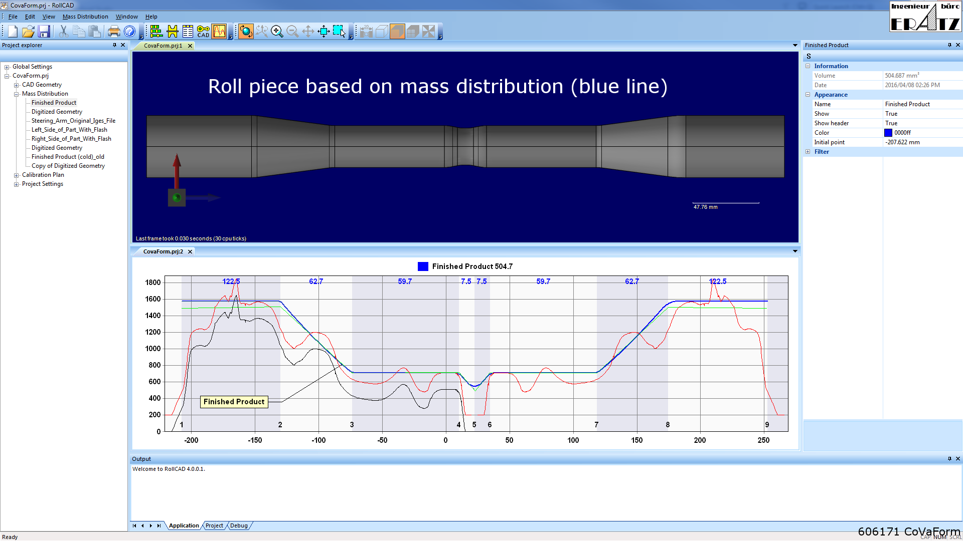
A 3D geometry is imported via a standard interface (IGES, VDAFS or STL). This results in a mass distribution and based on this diagram line a simple idealized roller part is generated. The part (finished part) is mirrored to achieve a stable cross wedge rolling process.
Manual design of a cross wedge roller part
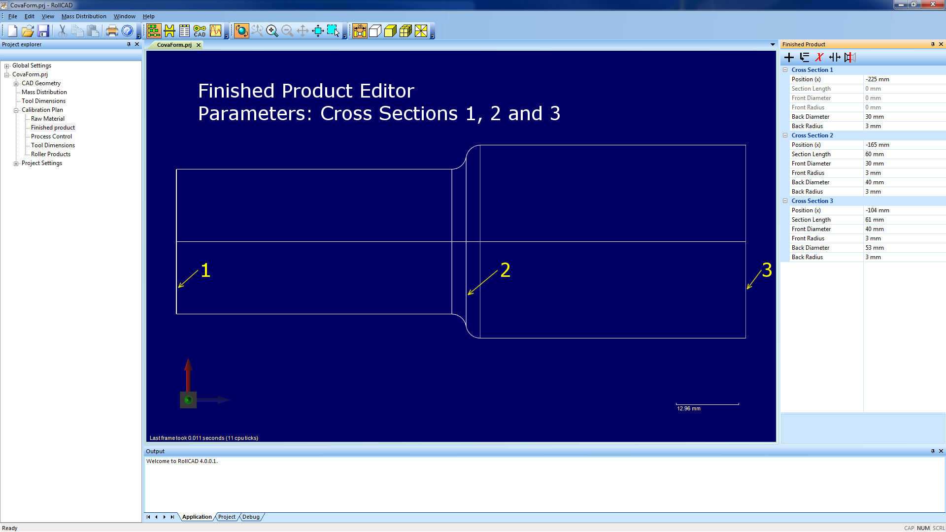
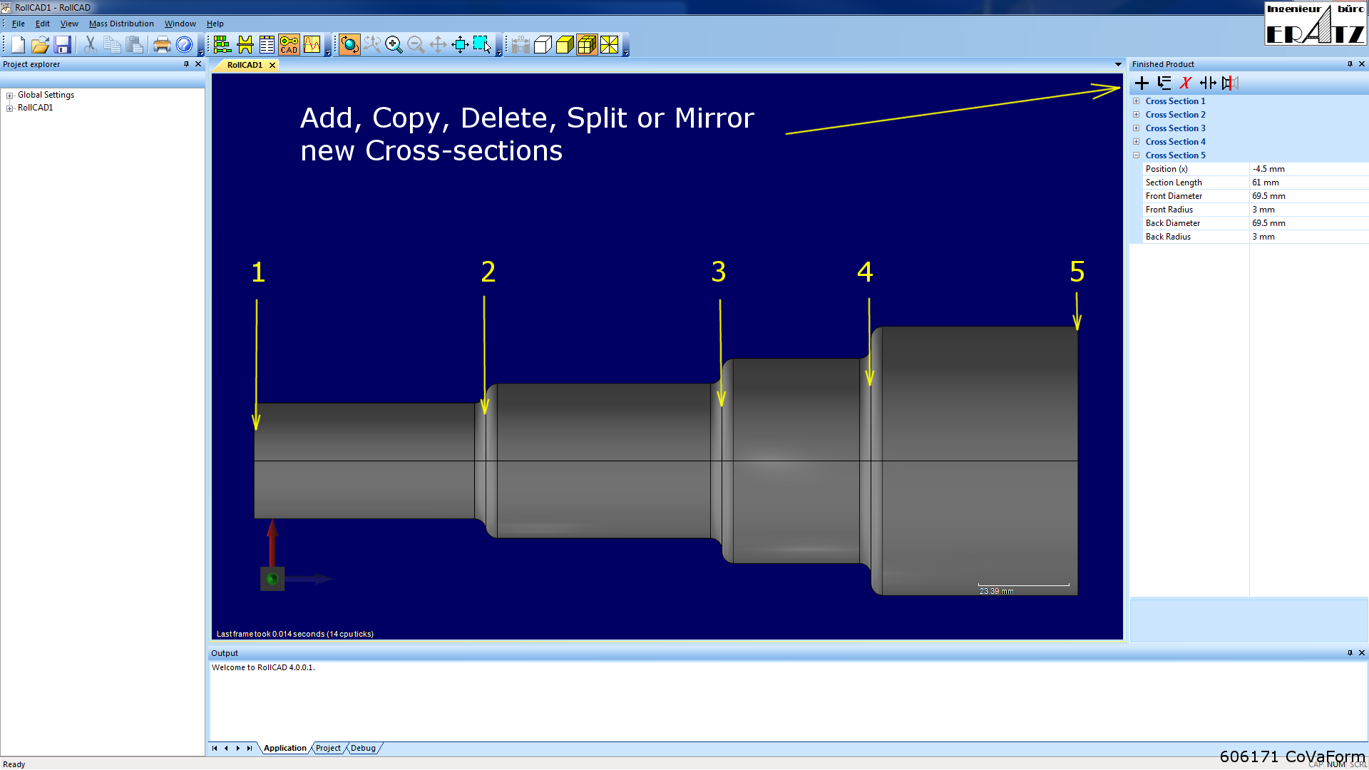
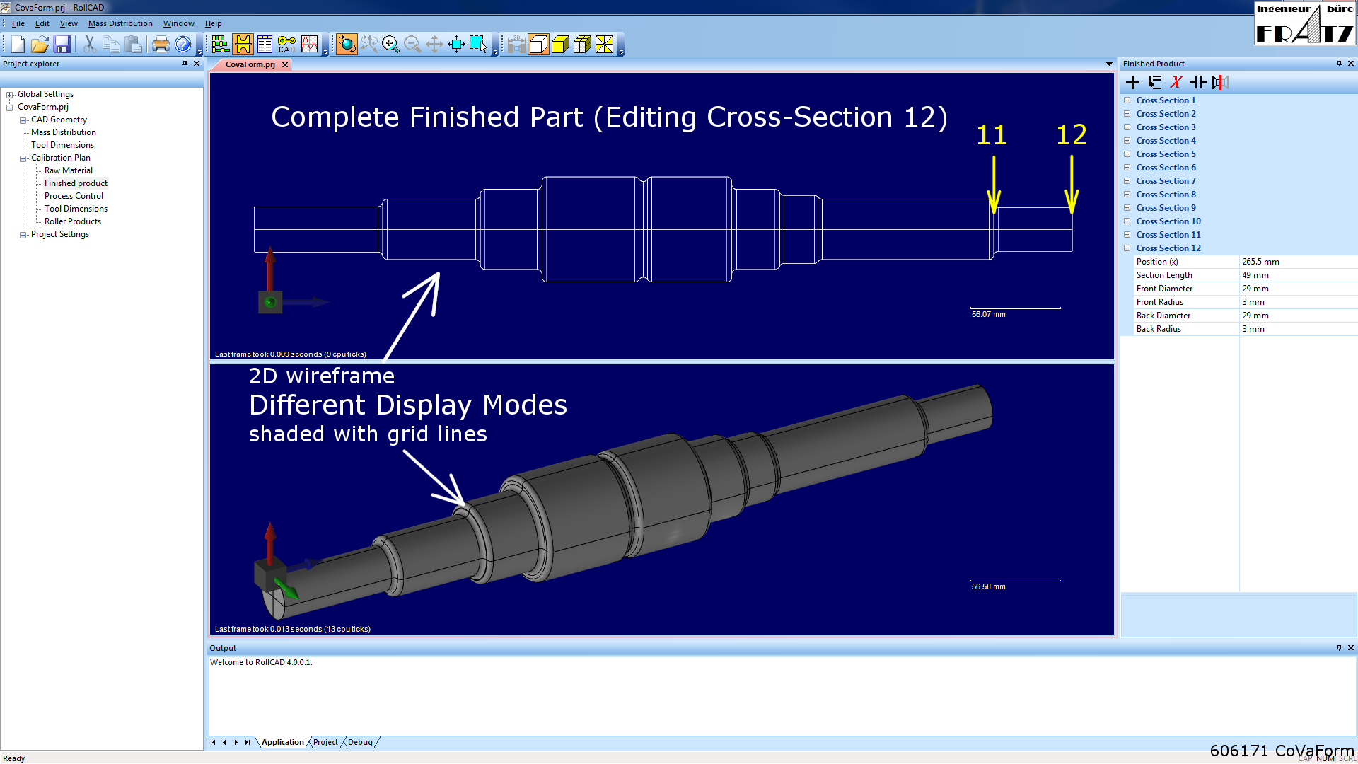
Alternatively, the cross wedge roller part is entered with the finished product editor.
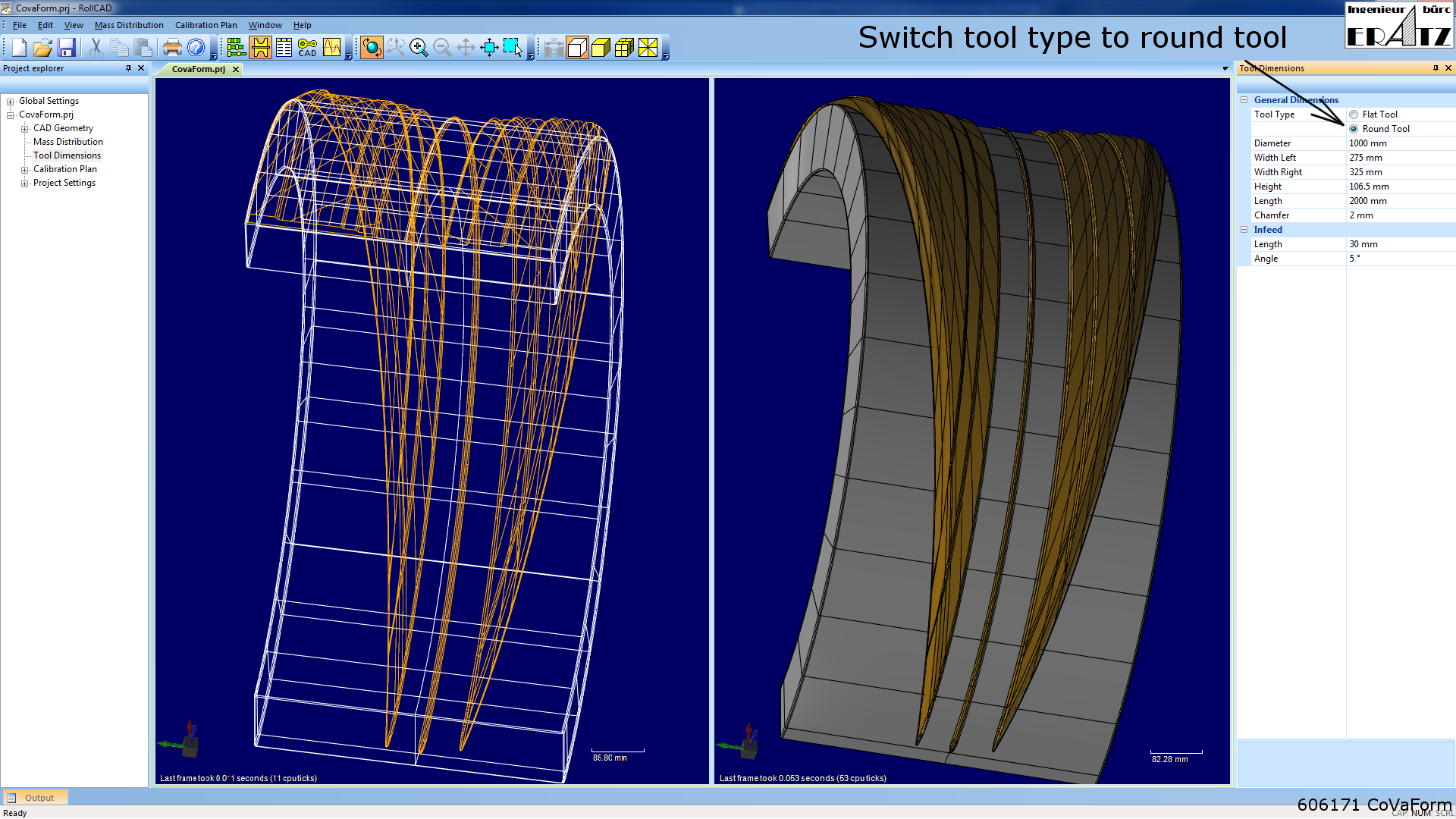
Defining the tool type as flat bar or round bar tool
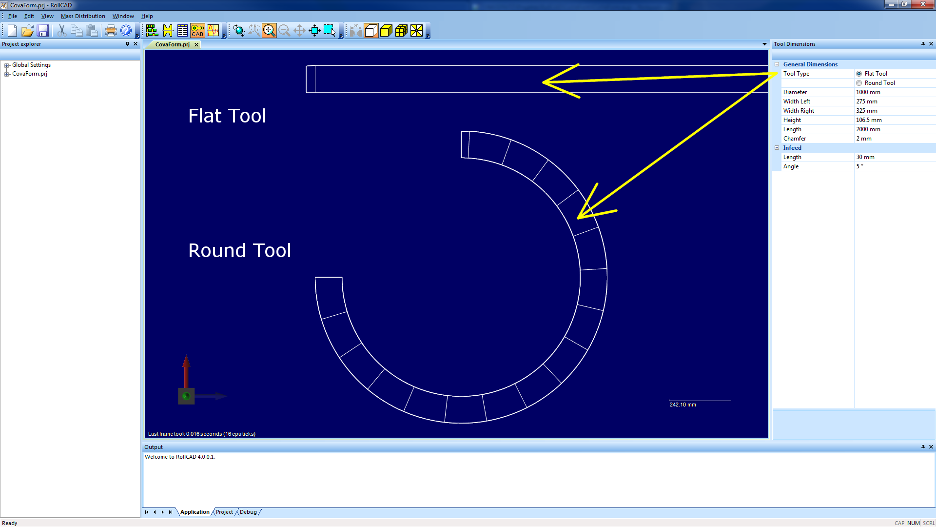
The design process allways starts developing the flat bar tool. In the next step the tool surface is unwound on a cylinder to get the round bar tool. This is done automatically with a single command.
Calibration plan
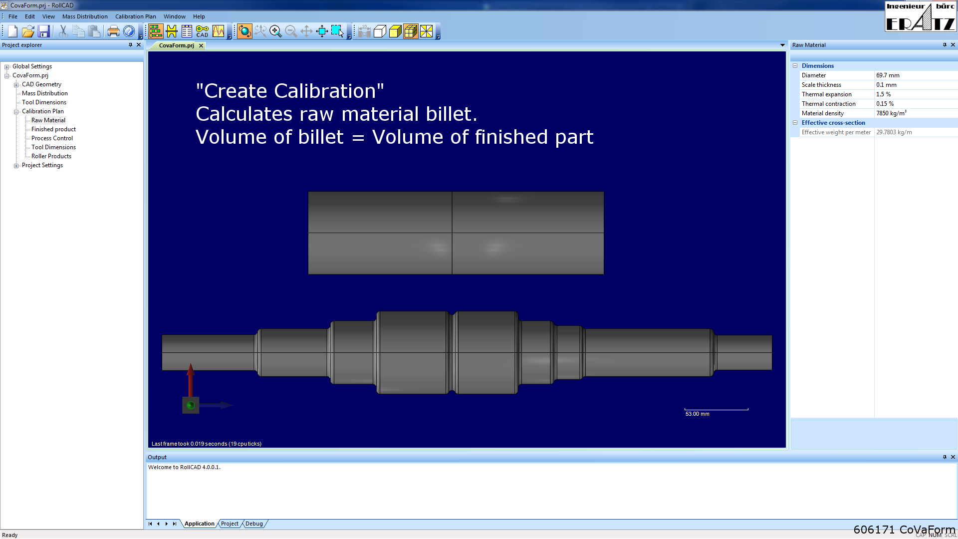
Start the project design of calibration plan with the command "Create Calibration". This will calculate the raw material billet with equal volume as finished product.
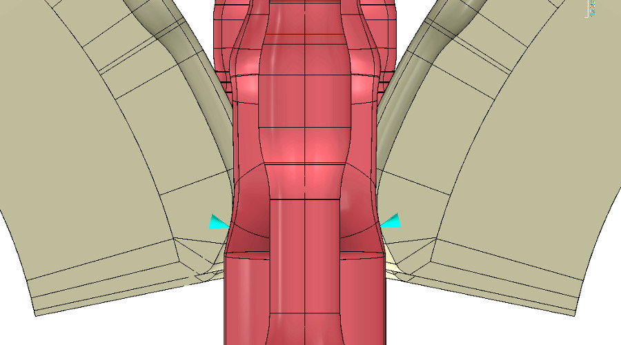
Design of deformation wedge
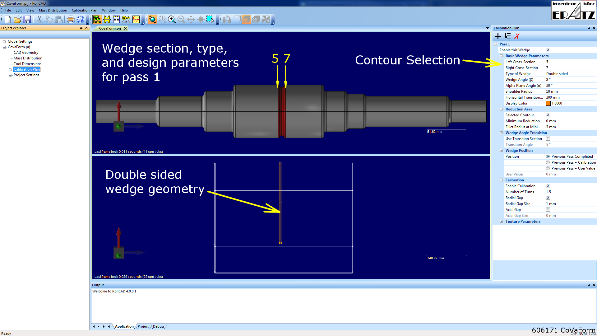
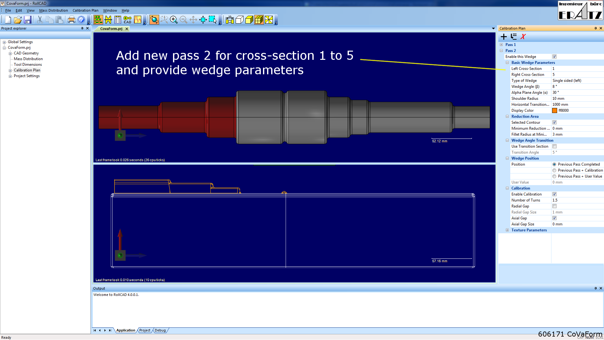
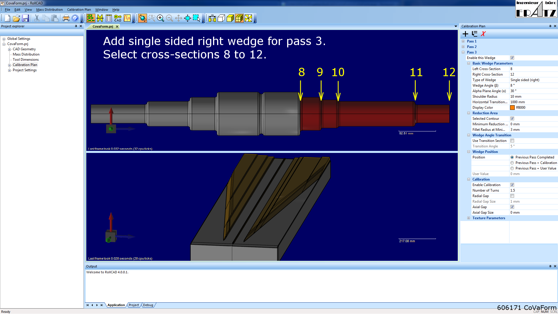
The shape and position of the wedges is specified manually. This requires special "know-how" about the cross wedge rolling technology.
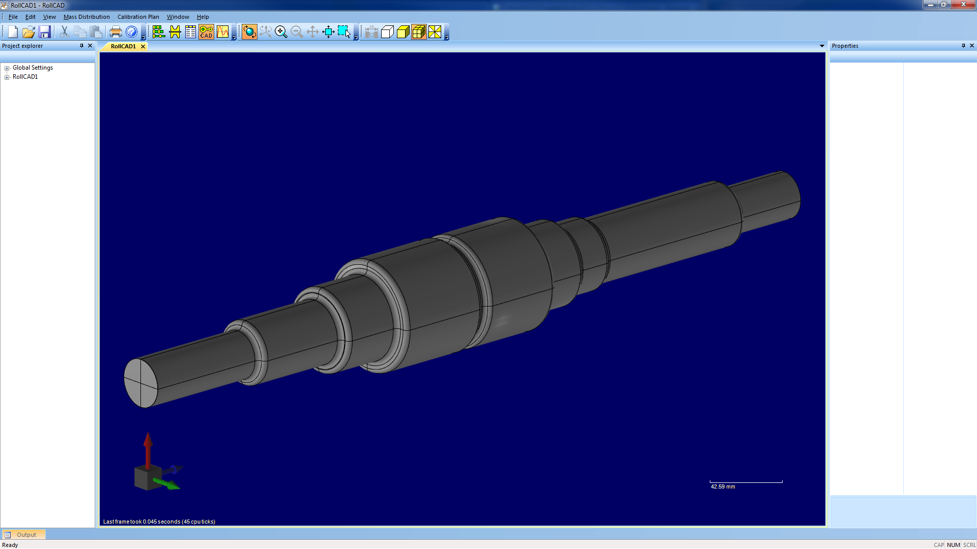
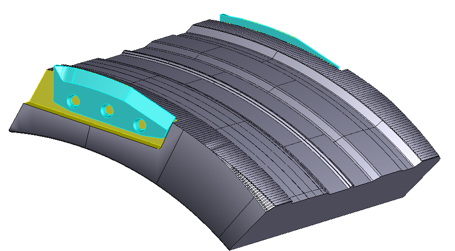
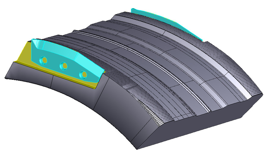
Flat bar and round bar tool
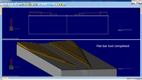
After all wedges are placed, the 3D geometry is automatically generated for both tool types.
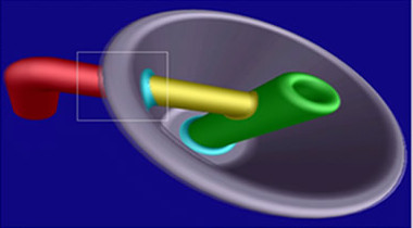
Deformation plane and cutting knifes
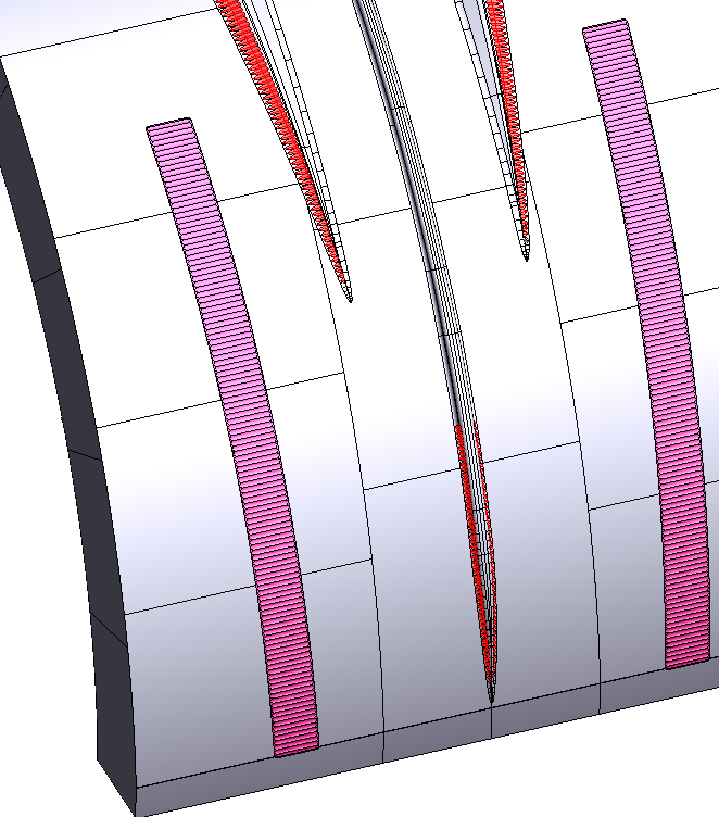
In further design steps, the corrugation on the "alpha plane" (deformation area marked in red) is attached, and the separating knifes added to cut off the end pieces.
Menu
Software
More
Imprint
ERATZ EngenieeringHerrmann Eratz
Kirchhörder Str. 94
44229 Dortmund
Germany
Phone +49 (0)231 72 73 290
Faxax +49 (0)231 72 73 291
E-Mail: he@eratz.de
© 2023 ERATZ Ingenieurbüro